26 October 2025

XT/AT power supplies and the wiring to the case power switch

Recently, I needed to connect a PSU up to an old style AT power switch. The push button type with four spade connectors and I needed to work out the wiring. It was tough to find anything definitive on the web when I was searching for information, so this post captures what I learnt in wiring up my AT power switch.

AT Power Switch

One of the PC’s I have put together needed a PSU I purchased on eBay to be wired up to the old-school push-button type power switch on the front of a separate old Viglen PC case I had brought on eBay.

Looking around on the internet there did not seem to be much information on the wiring of these so I’ve written this blog post to capture what I found in working to get this wired up and working.

WARNING!

Please remember that on these style of power supply switches these act as a basic on/off switch for the mains power to the PSU.

This means it is a live mains circuit running through this wiring so be VERY careful when handing it and the wiring to make sure it is not live!

 This post carries  a heavy disclaimer, as there are a lot of variances on this old XT/AT style equipment.

Electrical Shock Warning Label - Save ...

Wiring up the push switch

AT PSU wiring diagram to power switch

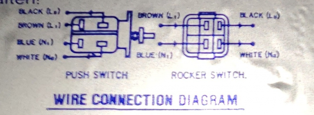
The switch connection from the PSU typically will have four leads with sometimes an optional fifth cable provides a ground lead to the case.

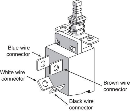
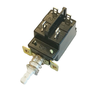
On some power switches, in particular it seems the push button type, you can often see that the spades on the switch correspond to a marked P1 and P2 connection on either side of the switch itself. These also seem to have a plastic ridge down the centre of them to help identify and provide a bit of isolation between the spade connectors.

One pair of these leads usually the brown and blue run from straight from the the power cord inlet socket on the back of the power supply.

Incoming mains supply:

  • Brown – Power cord hot
  • Blue – Power cord neutral

The other wires, usually black and white then run from the switch into the PSU to complete the circuit when the switch is placed into the on position.

Power supply to the PSU:

  • Black – Power supply hot
  • White – Power supply neutral

So when the switch is in the on position (pushed in), brown will be connected to black, and blue connected to white.

I did manage to find this wiring diagram on the side of an old PSU which provided some useful context.  The general guidance is that you should ALWAYS follow the wiring diagram on your PSU, see the example above.

As there wasn’t a clear defined standard at around the time these computers and power supply units (PSUs)  were being made – there could always be a manufacturer who decided on a different colour scheme for the wiring for a particular PSU. 

So be very careful and always go with the information on the actual PSU over anything else!

Sometimes one of the cables to the PSU could be a red colour I believe,  but I haven’t see one of these as yet to be able to confirm what this colour would relate to in terms of the actual wiring, hopefully your PSU will provide the answer.

In many cases diagrams seem to show the wiring on one side or the other of these switches.  As long as these wires enable the cables to be connected correctly to make the circuit they should still work even if on the other side of the switch.

A rough rule of thumb is that the black and blue wires should be connected diagonally opposite from each other.

However, if not cabled correctly then its likely you will end up with smoke and potentially blow or damage components.

Please be careful, if in doubt seek help and advice.

AT_Power_Switch_BEST

Also remember that it is a good idea to test any PSU will some type of load connected to it, for example a old hard disk drive that may not be fully working but will power up at least to provide this load.

For some PSU’s, for example those in the IBM PS/2 series, without a sufficient being detected load on the PSU they will not turn on and you may think you have a broken PSU when in fact you are just missing some load on it.

Useful note for XT clones

In a standard AT motherboard power connection pinout (P8/P9), pin 2 on the P8 connector carries a +5V DC.

On an IBM XT motherboard, this pin is not connected.

So some XT clones motherboards may not correctly handle the +5V signal on this pin and can fail to boot, so you may need to remove this pin from the P8 connector. 

This took me a few days to work out – I though the particular XT clone motherboard I was working on was dead; when in fact it was just this unnecessary signal connection preventing it from powering up.  I can’t remember ever running up against this one before so this was a new lesson learnt!