C64C Short-board (250469 – 2523311 Rev 3) repair
Sean Lewis 30 June 2024The story of my first attempt a repairing a C64 short board motherboard
The story of my first attempt a repairing a C64 short board motherboard
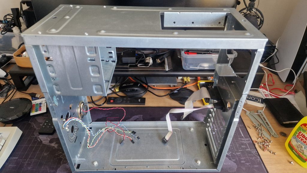
So having recently after a lot of should I or shouldn’t I debating with myself over the years and watching a lot of C64 repair videos, I succumbed and picked up some second hand Commodore computers.
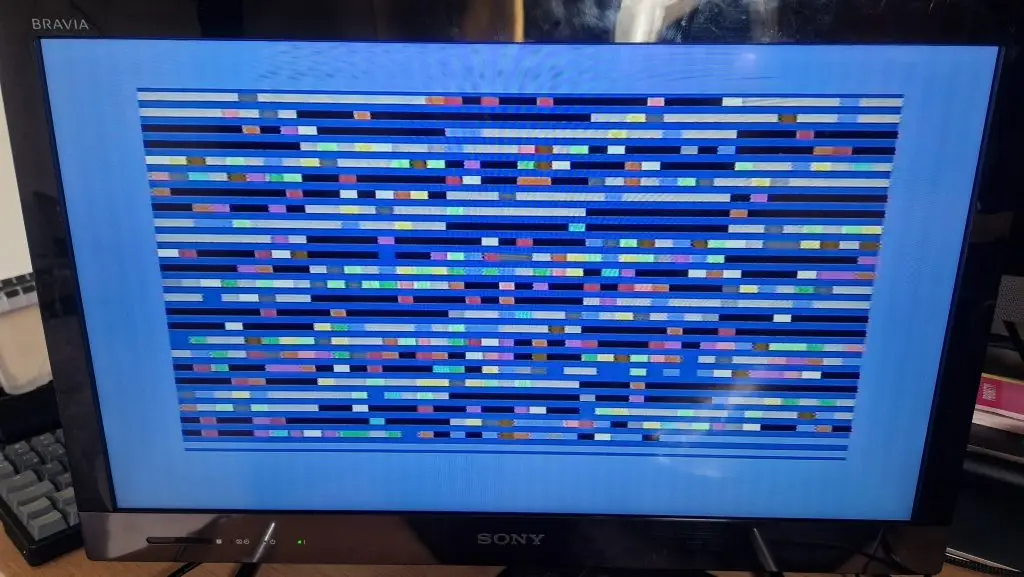
One of these computers did not start correctly and as you can see in the picture would often display a multi-coloured set of bars in the screen display area. A lot of the time the machine would just start to a black screen.
So inspired from a lot of Youtube watching I decided to take on the project to try and bring this board back to life.
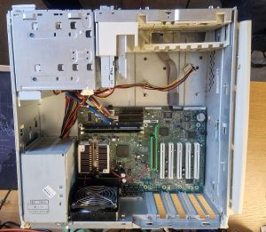
Luckily in picking up the set of second hand C64s I had also acquired a similar C4C short board machine but this one had the Rev 4 board but was fully working, and gave me access to some working chips to test with as well.
After some oscilloscope probing and swapping a couple of the chips over, mainly the VIC-II chip as a test, I could not clear the symptom, although the screen had now changed to occasionally showing alternative light and dark blue rows across the screen.
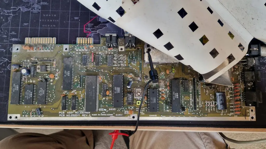
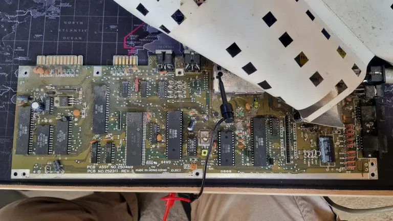
So my testing brings me to a point where I need to obtain some replacement chips and socket them to the board as I’m swapping them out. Soldering at this point is something I am re-learning after a number of years so this is going to be a cautious approach as I would not be happy to damage the actual board.
So my first point of call from the investigations so far point to it potentially being a issue with CIA 2 which means finding a 6526A chip. It could also be a problem with the MMU (super PLA without the integrated colour RAM), but as these are a bigger chip and more expensive I though I would start with ordering some CIA chips first.
So my replacement CIA chips arrived, in the end I decided to order a pair of J-CIA chips, working on the assumption that I may need another one at some point so saved on the international postage and ordered them at the same time.
At this point the CIA 2 chip is a likely cause of the problem, but as I’m not 100% convinced I don’t want to cut the legs of the chip to remove it, so I’m attempting to de-solder the chip from the board. Armed with a soldering iron and a de-solder pump, I made a start but only achieved limited success in removing enough solder from around the legs around 30% of the time. Not wanting to do to much damage I’ve invested in a better (although still relatively cheap) vacuum pump which should turn up in the next day or so. I hope this well help me to get more of the solder out and hopefully protect the CIA chip from any damage. I also found someone selling a super PLA chip for a reasonable price on eBay so I’ve ordered that as well to add to the spare chip collection.
In a moment of madness I’ve also now acquired an Amiga 500, so I know have another machine to add to the restoration projects. Still need a VIC-20 at some point though.
So today was an adventure in de-soldering the CIA chip. Definitely works better than the hand head spring-loaded ‘pump’ using the new vacuum pump version, a worthwhile investment I think.
After learning the wiggle it around on top of the solder, technique and getting the heat setting right (300C) the solder started to come out of the pin holes pretty easily and quickly. Not sure if its a feature of the short-board but the ground pin was very well anchored in place, and for a long time there some solder that just would not come out of the pin-hole no matter what I tried. Perseverance won in the end but it was a tough battle and I though at one point I might have to try something more direct to get the solder out, but success was achieved in the end.
Putting in a new socket for the chip went well and I was quite pleased with that result. Unfortunately even with one of the new J-CIA chips in the socket the same symptoms appears to be happening, so that CIA was not the cause, so the investigation continues.
Now I have the one CIA chip in a socket, against popular wisdom I think I’ll remove and then add a socket for the other CIA chip as well.
I think the next most likely cause could be the super-PLA chip so more practice on the other CIA chip might be a wise step before attempting that more delicate operation on the board.
And so the journey continues …
So having de-soldered the other CIA chip, having now started to learn that applying some flux and new solder helps the process along enormously I find myself making good progress on the board. Some of the solder can often be stubborn which requires and increase of the temperature on the vacuum pump from the 300C to 450C to get it to melt sufficiently which makes me nervous but seems to do the job, possibly due to this older solder containing lead so it has the higher melting point.
Re-inserting the CIA chip with one of my new J-CIA chips in the other socket, resulted in a black screen which was not good.
However having two J-CIA chips socketed at the same time did get the screen to come back into a better state, but not a perfect one as yet as can be seen in this picture.
The dead-test runs mostly clean but as I don’t have the moment have a test harness some of these will show as a fail, but nothing major.
So something appears to be wrong with the video display as these flickering dots appearing on the screen are showing a symptom that now needs to be chased down.
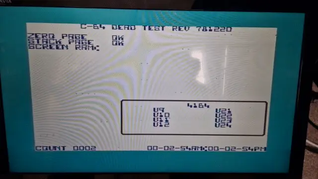
I also think the character ram may have some damage as the start-up screen shows some extra characters in the banner message for some reason, but I’m going to go after the screen symptom first.
On a plus side the super-PLA chip isn’t one I’ve had to tackle …. yet.
Continuing the theme of putting chips into sockets, my next area of attention were the two dram chips at U10 and U11 as I though these would be a quick and easy set to socket. However this was not the case and these did not come out of the board cleanly and frustratingly received some damage. So I’ve had to order some new replacements for these and some 18 pin sockets for them to go into, so I’m currently waiting on a delivery of some of these to get these installed and check that the board is still OK after lifting these out.
The repair journey continues on. So having socketed two new DRAM chips in the board, it seems things have taken a small step backwards.
I seem to be getting a black screen on startup and so far have only been able to get any sort of display working briefly once. The dead test cartridge does seem to work and gives my a single flash but I doubt this is actually related to the DRAM as I have tested it with a four different sourced chips, although I don’t have a way of testing them to check so I’m taking those a little on faith at the moment until I get to scoping around the pins on the chips.
The VIC-II chip does seem to running very hot very quickly, faster than I remember, but does work OK still in another short board C64C so for now that rules that chip out as a cause.
Its increasingly looking like its going to be time to check around the board and chips with an oscilloscope next as its getting nearer to the likely culprit of the PLA chip as the potential cause, but I still want to try and rule that out as much as possible before I go down that step.
So its been a little while, so time to catch up and where I have been able to get to. I decided to go a bit all on on the board and re-socketed the Kernel, Char ROM and PLA in one fell swoop. The good news is that the work went went and hasn’t seemed to make anything worse. The bad news is that even with a different PLA in the socket, I still received the dread single-flash from the dead-test cartridge. This seems to be the case for this revision of board that the error is somewhere in the Data Bit 7 net, but testing around the board with a multi-meter didn’t find anything untoward to point to an obvious error like a bad solder or loss of connectivity/continuity around the re-socketed or data bit 7 paths on the board that I can see.
If it seems like that hasn’t been a lot in the time since the last update to this post, that is mainly due to me working on the Amiga 500 and C64C/BMC64 projects I also have going on, more details to follow.
For now this is where the post ends, I’ll provide an update on progress after checking around the board with the oscilloscope.
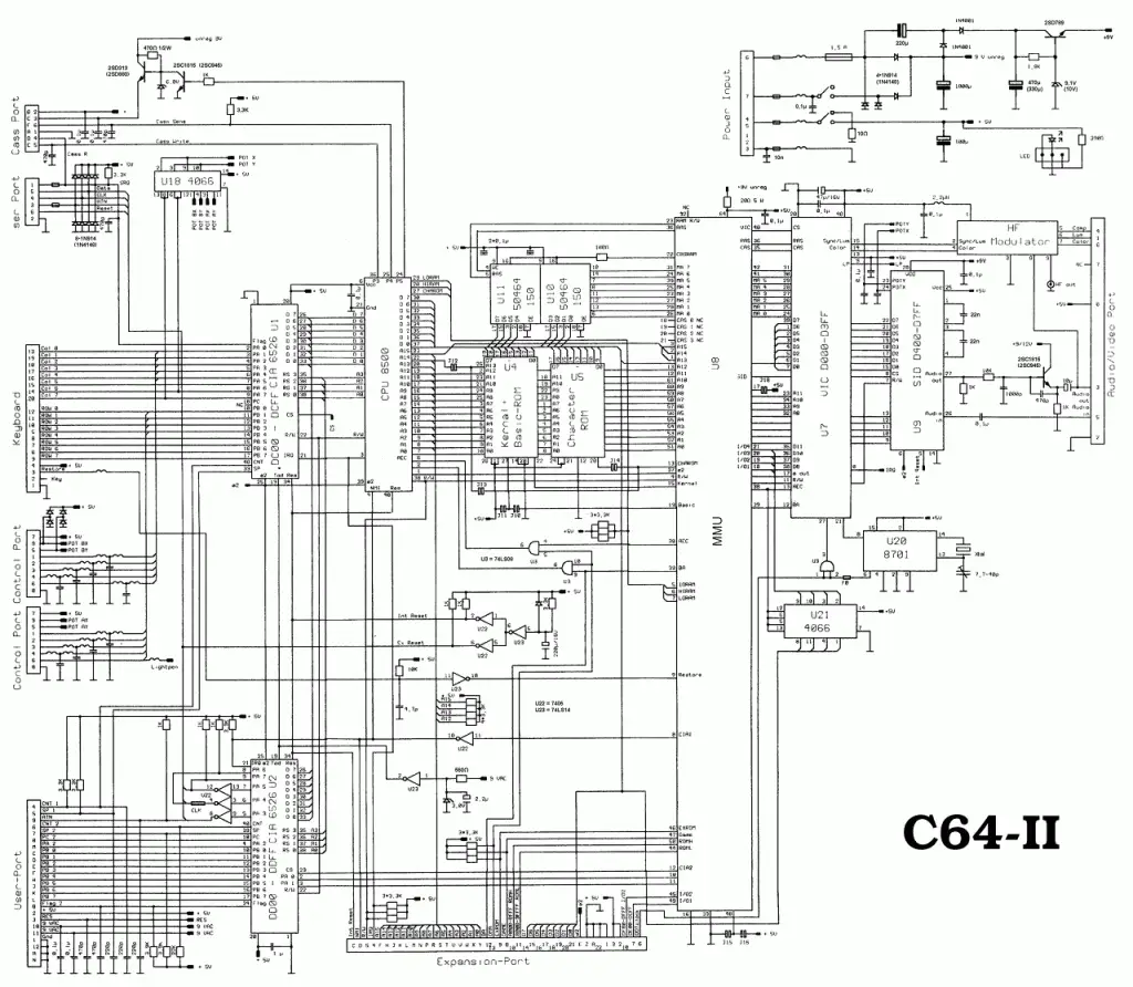
Integrated Circuits on PCB assembly number 250469 schematic number 252311 rev 3
| PCB Identifier | Chip Number | Remarks | Memory Location/bit |
|---|---|---|---|
| U1 | 6526A | CIA 1 | $DC00-$DCFF |
| U2 | 6526A | CIA 2 | $DD00-$DDFF |
| U3 | 74LS08 | ||
| U4 | 23128 | Basic and Kernal ROM | $A000-$BFFF $E000-$FFFF |
| U5 | 2332 | Character ROM | $D000-$DFFF |
| U6 | 8500 | CPU | |
| U7 | 8565 (PAL) | VIC-II | $D000-$D3FF |
| U8 | 251715-01 | PLA | |
| U9 | 8580 | SID | $D400-$D7FF |
| U10 | 41464 | DRAM 64Kx1 | D0..D3 |
| U11 | 41464 | DRAM 64Kx1 | D4..D7 |
| U18 | 4066 | Quad Bilateral Switch | |
| U19 | 2114 | SRAM 1Kx4 (Colour RAM) | $D800-$DBFF |
| U20 | 8701 | Oscillator | |
| U21 | 4066 | Quad Bilateral Switch | |
| U22 | 7404 | inverter | |
| U23 | 7404 | inverter |
Items shown in bold were replaced to fix this particular boards issues.
Links
https://www.pictorial64.com/
https://www.zimmers.net/anonftp/pub/cbm/schematics/computers/c64/index.html
https://ist.uwaterloo.ca/~schepers/MJK/c64__.html
https://www.youtube.com/watch?v=DiG_BLQW2gw
Commodore 64 (ASSY 250469) Board Repairs